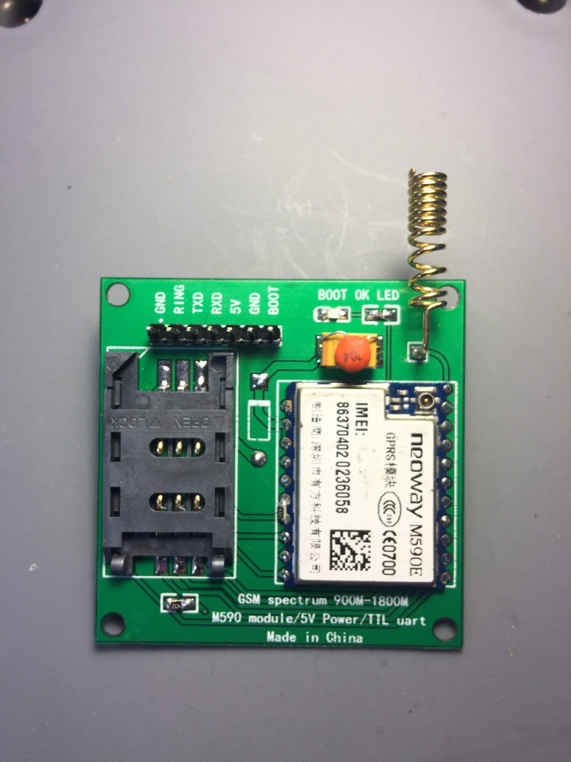
The M590E is a 2G GSM module that, at the time of writing, can be bought as a kit on eBay for around £1 complete with PCB and components.

Fig.1 M590E kit before assembly
The kit is quite straightforward to build, the only tools you will need are: fine tipped soldering iron, solder and a pair of small wire cutters.
Unfortunately the kit, as it stands is not designed particularly well, especially if you want to use it with a 5v system, such as an Arduino. The main problems that need addressing are:
1) The module is designed to be powered from between 3.3v and 4.5v. The kit contains a series diode and suggests you power it from 5v. A forward biased diode will drop approximately 0.7v this powering the module at 4.3v. Using a diode in this manner is not ideal and the data sheet advises the best voltage for the M599E module is 3.9v
2) The power rail for the module has a single 100uF capacitor, the data sheet advises additional capacitors to eliminate rf noise.
3) The serial data receive pin cannot have more than 3.3v applied to it, without risking damage to the module, but the kit simply brings the rxd line straight out to the header pins. It needs some additional circuitry if we are to connect it to a 5v / TTL system.
4) The serial data transmit pin again is brought straight out to the header. The data sheet advises a series resister to protect the module.
See figure 2 for the circuit diagram of the kit before modifications.
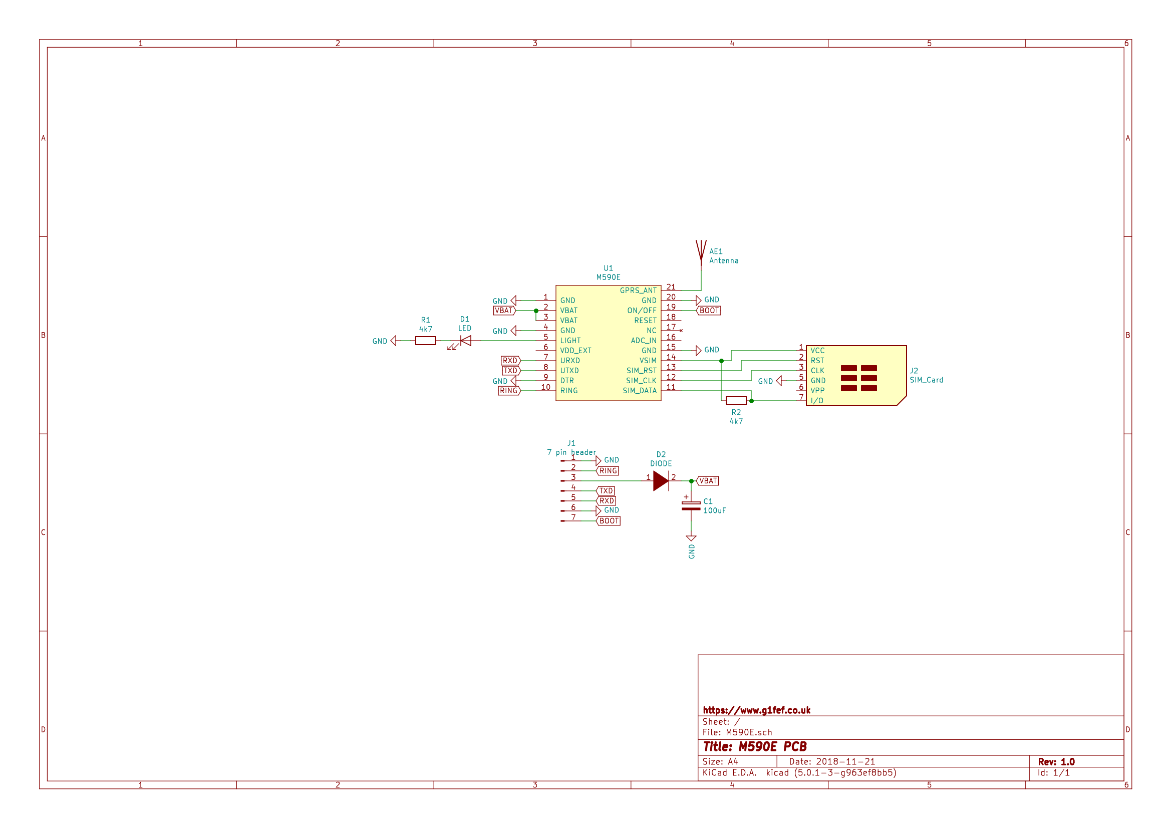
Fig.2 – Original PCB Circuit
See figure 3 for the circuit diagram after modifications.
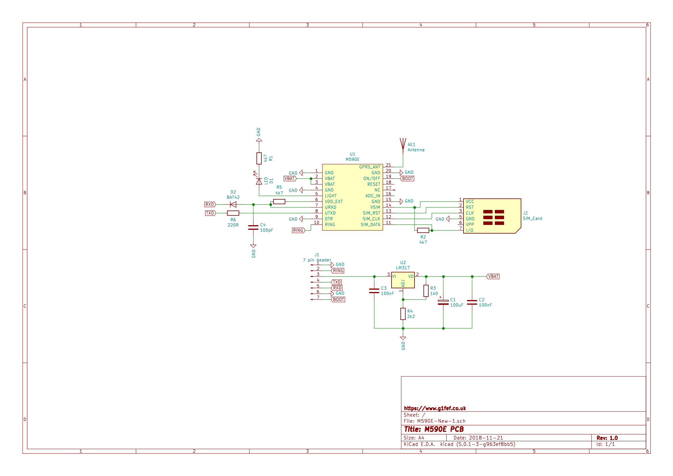
Fig.3 Circuit diagram after modifications
To address the first problem, I added an LM317 voltage regulator to the PCB to provide a regulated supply rail. This has the advantage that you can supply the board with any voltage between 6.25v and 44v. The disadvantage is that you cannot power it from 5v which many people may prefer due to the prevalence of low cost 5v power supplies. The LM317 loses between 1.5 and 2.25 volts across it at room temperature, depending on the current being pulled through it (see figure 4 taken from the datasheet).
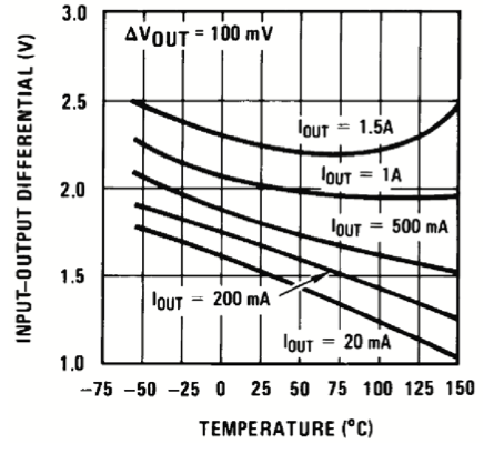
Fig. 4 – Graph of LM317 dropout voltage
I investigated using a low dropout (LDO) regulator, the LM1086 is a pin-compatible replacement that has a maximum of 1.3volts dropout at full load (1.5Amps) and only 1.0volts dropout at 500mA, so it could be used at a push as the M590 module only pulls high currents when it is transmitting and then only in short pulses. If you replace the 100uF capacitor on the PCB with a 1,000uF capacitor you could use an LDO regulator and supply it from 5volts. I have tested this successfully, I used the LM317 because it is cheaper and I intended powering it from a 12volt battery. Incidentally, the LM317 does not require a heatsink due to the intermittent nature of the higher current drawn by the M590 module.
The second issue was addressed by adding a 100nF ceramic capacitor across the 100uF capacitor.
The third issue was addressed by adding a diode and a pull up resistor (D2 & R5) in the second circuit diagram (Figure 3). If you use a surface mount device for R5 it can soldered directly between pins 6 & 7 on the LM590 module. Pin 6 outputs 2.85 volts when the module is running.
The fourth issue is solved by adding a 220R series resistor, R6. The datasheet suggests 200R but 220R is a more commonly available value and works just as well.
The modules I modified were to be used for remote data logging. An Arduino Nano was used to collect the data and sent the data on demand via SMS. I wrote a sketch that waits for a received SMS message, it then sends the current data back via SMS. I wanted the M590 modules to boot up as soon as power was applied, so I soldered the BOOT pin directly to GND. In this configuration the module will boot up as soon as power is applied.
Modification Details
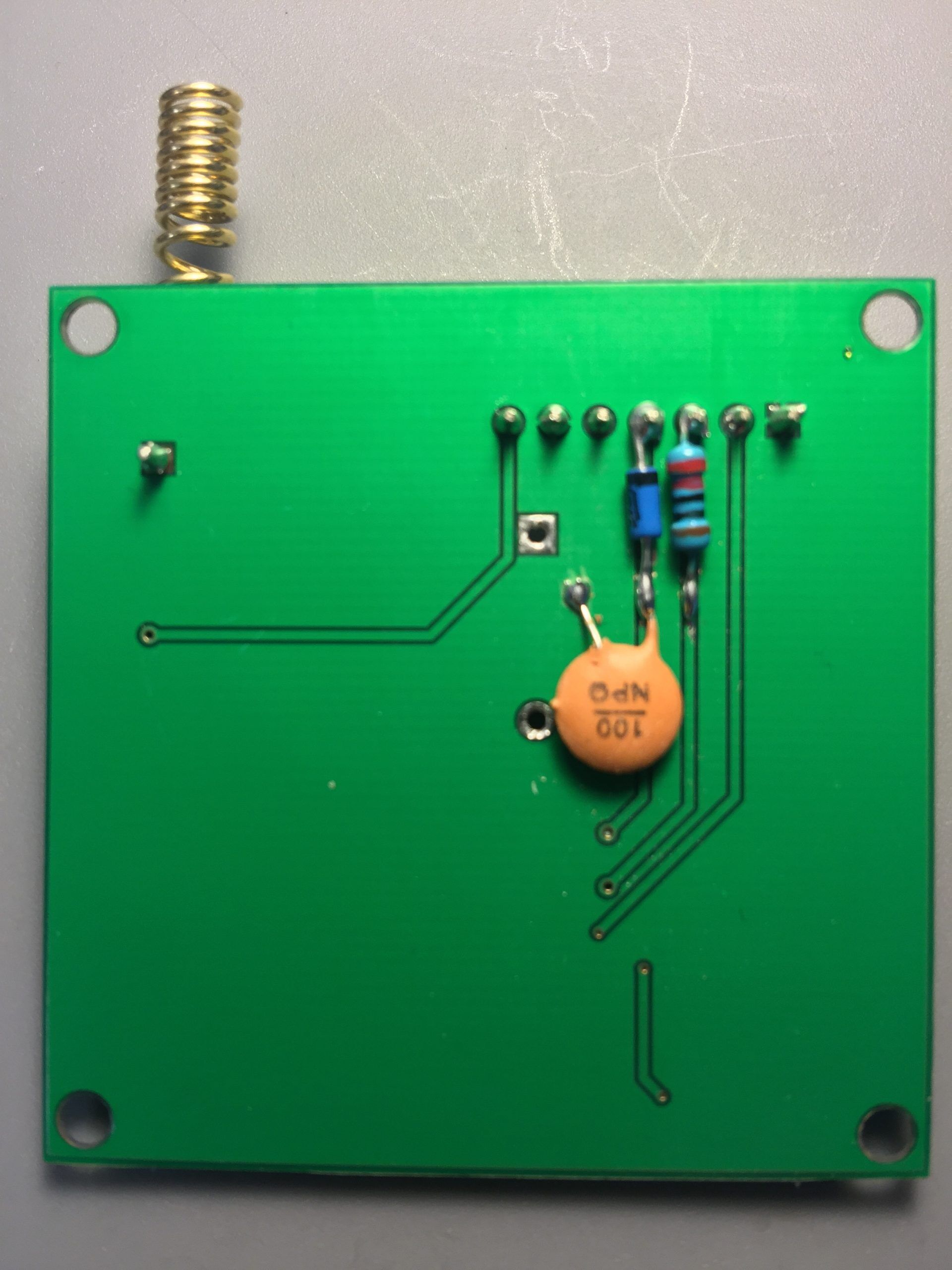
Start by carefully cutting the TX & RX tracks with a Stanley knife:
Cut the TXD & RXD tracks
Then add D2 (BAT42) and R6 (220R).

Add D2 & R6
Now you can add C4 (100pF):
Add C4 (100pF)
Add C4 (100pF)
The LM317 adjustable voltage regulator goes in next:
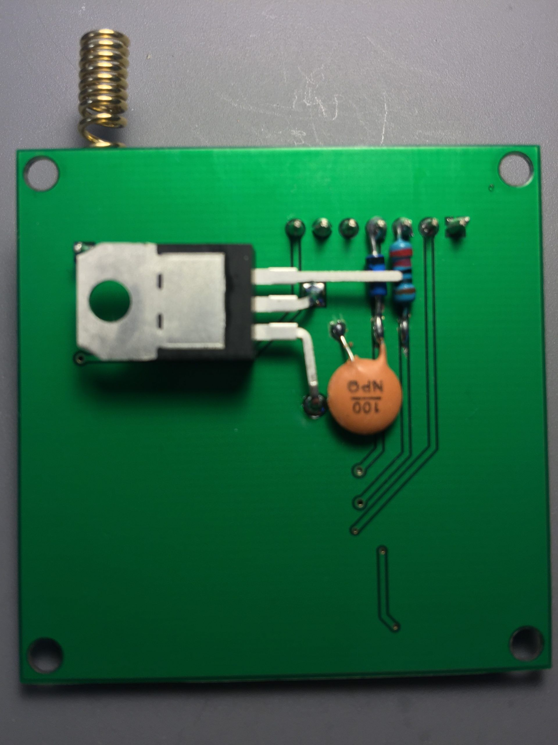
Add LM317
Now add R3 (1ko) & R3 (2k2), followed by C3 (100nF):
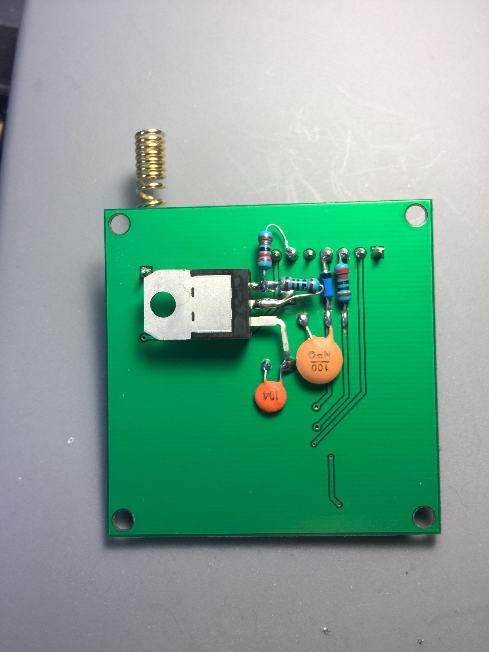
Add R3, R4 & C3
Finally add C2 (100nf) across C1 and R5:
Add C2
Testing
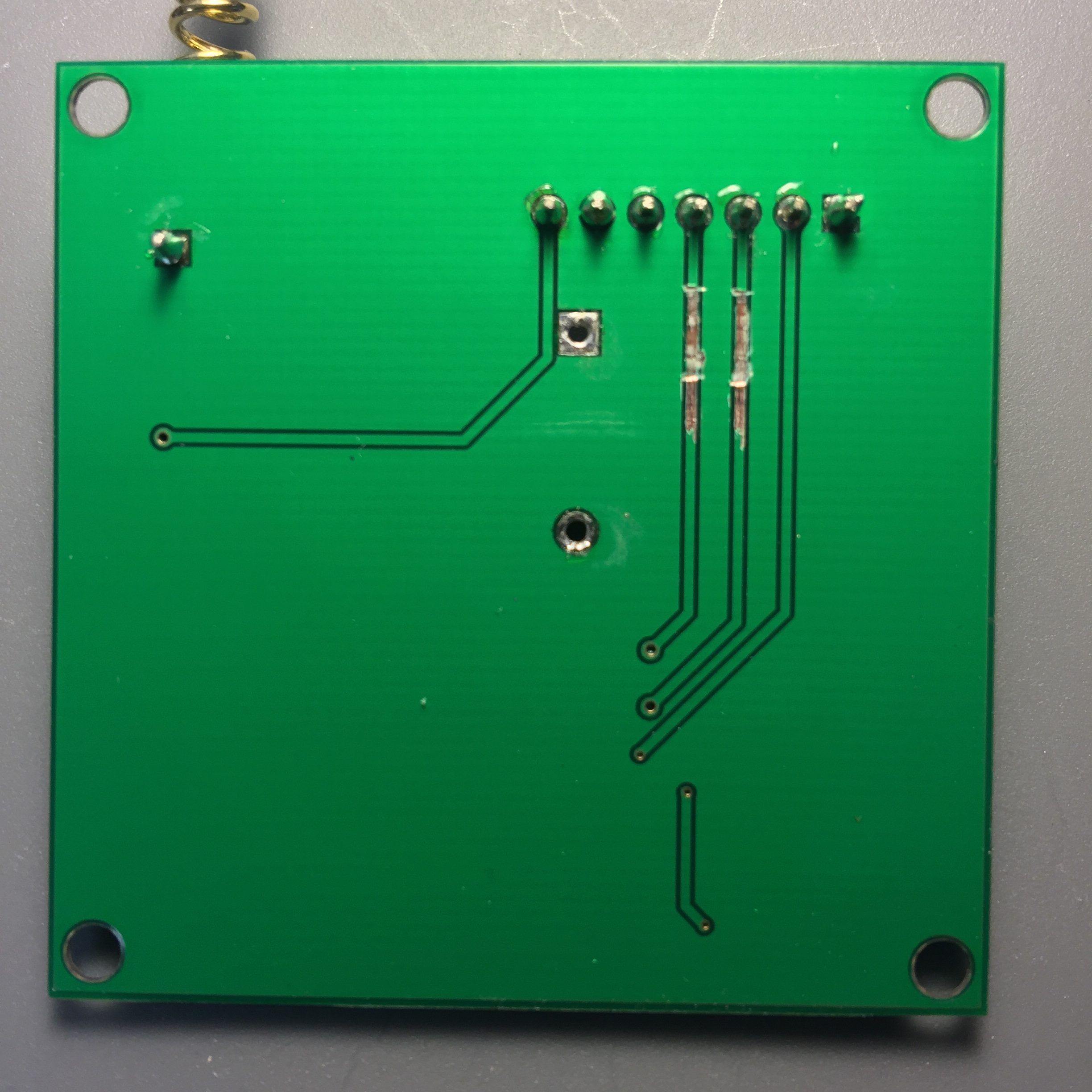
From the photo’s you can see that I modified a PCB that I had already built. My advice would be to do the modifications BEFORE building the PCB! Once you’ve done the mods, check the voltage on VBAT (pins 2 & 3 of the M590E module), it should be 4.0 volts (or very nearly).
Now you can add your SIM card, I use GiffGaff (www.giffgaff.co.uk) as they are about the cheapest you can get here in the UK.
I tested the unit by connecting it to my iMac via a TTL to USB board, available from ebay for a couple of pounds. The units default to 115200 baud. Try sending “AT” followed by a carriage return, you should see “OK” returned if all is well.
Once I had tested it was working on my Mac, I hooked it up to an Arduino Nano using the SoftwareSerial library (built into the core since v1.0). I found, by trial and error, that a baud rate of 38400 is about right: too high and the software serial library starts to miss characters, too low a rate and the Arduino spends too long in interrupts and the main loop is affected.